Sizewell C cooling water system
The new nuclear plant at Sizewell C, East Suffolk, has a key role to play in securing a low carbon future for the UK. It will power 6 million homes using two new generation European Pressurised Reactors. Our guidance has helped to optimise the design of the plant’s critical cooling water system.
Cooling water at Sizewell C will be drawn from the sea by four submerged intake heads, and released through two submerged outfall heads. These concrete structures are located on the seabed some three kilometres from the shore.
HR Wallingford’s expertise in sedimentation, coastal hydraulics, computational fluid dynamics (CFD) and physical modelling underpinned the robust guidance we provided for the design of the cooling system. Our advice was used to:
- optimise the layout of the intake head to help reduce the impact of the new structures on the local flow conditions, and therefore the local marine environment
- address sedimentation inside the cooling system to help design a resilient hydraulic system that considers the risks of increased head loss and needs for maintenance
- deliver valuable wave pressure and force data that will ensure a vigorous structural design of the intake and outfall submerged heads
- ensure the stability of foundations by testing the seabed scour protection
- minimise air entrainment and related risks in the outfall tunnel through optimisation of the outfall structure design.

Investigations indepth
Sizewell is exposed to waves generated across the North Sea and Atlantic Ocean. HR Wallingford carried out a joint probability and wave transformation study using UK Met Office offshore data to derive extreme wave heights and water levels at the location of the intake and outfall heads; these informed the engineering design of the structures.
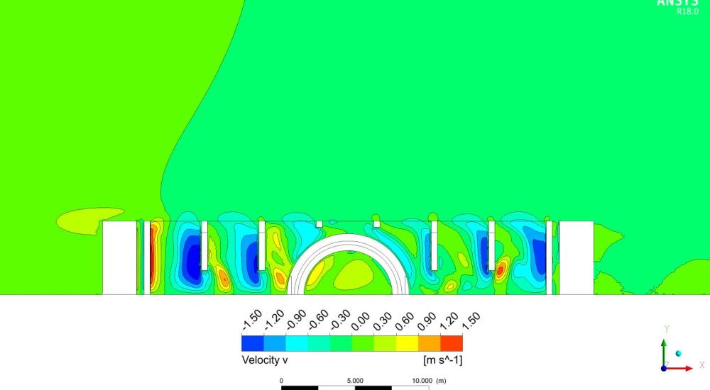
Using advanced CFD models, our team explored flows around 10 different intake head designs and identified the best design option in terms of head losses, flow distribution and side-entry velocities.
We identified areas where sediment was deposited in the intake and in the pumping station forebay onshore to support the siltation assessment for the cooling system.
We developed a 1:40 scale physical model of the seawater intake and outfall and tested them in the 1:100 year and 1:10,000 year return period storms. We measured wave loads on the heads and on internal walls of the seawater intake, as well as pressures; these were used to calibrate the twin OpenFOAM CFD model. The 3D pressure maps from the CFD model were used directly in our client’s structural analysis software. We also used the physical models to check the stability of the scour rock protection to be placed on the seabed around the heads.
We built a 1:20 scale physical model of the outfall building, which collects all the spent cooling water before discharging it back to the sea via the outfall tunnel. The design of the weir and the entrance to the drop shaft were modelled under normal operation and maintenance flow rates to assess the hydraulic performance and the risks of air entrainment into the outfall system.
Want to know more?
Contact our project lead

